What is a 1-phase 2-wire electric meter?
A 1-phase 2-wire electric meter (electric meter) is a device used to measure the electricity consumption of each household. There are currently two types of 1-phase electric meters:
- Mechanical 1-phase electric meter: This type is widely used due to its simple structure, easy installation, high durability, and reasonable cost.
- Electronic 1-phase electric meter: This type of meter is highly accurate, can measure many related parameters, and has the ability to detect electricity leakage.

The device consists of:
- Voltage coil: Installed in parallel with the load, with multiple turns of wire, and the wire diameter is smaller than other meters.
- Current coil: This part has fewer turns than the voltage coil but has a larger wire diameter.
- Aluminum disc: Installed above the axis and fitted into the spindle to rotate freely between the voltage coil and the current coil.
- Permanent magnet: This part generates torque when the aluminum disc rotates in its magnetic field.
- Mechanical gearbox: Its task is to display the number of rotations of the aluminum disc when connected to the axis of the aluminum disc.
Working principle of 1-phase electric meter
When electrical devices are used, the components of the meter begin to work. A magnetic field is generated under the aluminum disc as a result of the current passing through the wire loops, with a relay connected to the mechanical display.
Under the influence of the magnetic field from the voltage coil, a torque is generated, causing the aluminum disc to rotate in the permanent magnet and creating a counter-torque to maintain the balance of rotation.
Through this process, an electricity consumption index is generated based on the rotations of the aluminum disc. The rotating aluminum disc causes the number wheel to move, displaying the electricity consumption index on the surface of the load.

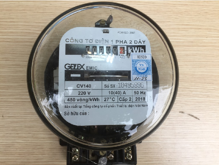
Meaning of the parameters on the face of the 1-phase electric meter
- 220V: Rated voltage of the electric meter.
- 10(40)A: Rated current of the 10A electric meter. If the usage exceeds 40A, the electric meter will not guarantee accuracy and may be damaged.
- 450 rotations/kWh: One kWh corresponds to 450 rotations of the electric meter disc.
- Class 2: The accuracy level of a meter with an error of only 2%.
- 50Hz: The frequency of the power grid is 50Hz.
How to connect a 1-phase electric meter correctly
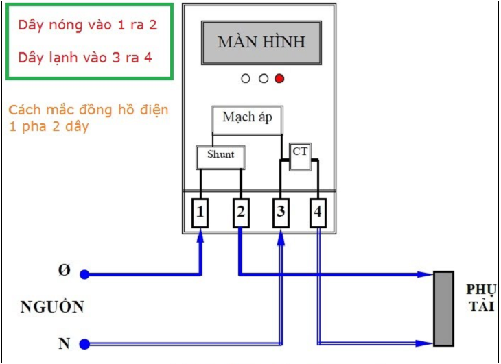
Diagram of connecting a 1-phase electric meter
- Wire 1: Symbol for incoming hot phase wire.
- Wire 2: Symbol for outgoing hot phase wire.
- Wire 3: Symbol for incoming neutral wire.
- Wire 4: Symbol for outgoing neutral wire.
[info]Note: Wires 3 and 4 are connected together. To determine the hot phase wire, users need to use a test pen. If the wire the test pen lights up is red, it is the hot phase wire.[/info]
How to connect a 1-phase electric meter
Connecting a 1-phase electric meter is quite simple. Please follow these steps:
- Step 1: Use two hot phase wires to connect to positions 1 and 3.
- Step 2: Next, use two neutral wires to connect to positions 2 and 4.
- Step 3: Then, connect the two output wires (wire 2 and wire 4) to the circuit breaker.
- Step 4: Finally, double-check and power up the meter for use.
This article has provided you with a safe and technically correct way to connect a 1-phase electric meter at home. If you have any questions, please leave a comment below and we will be happy to assist you!


